AIR BORN, the demo Sage 17, spends a lot of time on the water. During the Colorado sailing season, about late May through late September, she is usually on Lake Dillon in a slip in the Dillon Marina. When at the lake she is fully rigged and ready to sail. When not at Dillon, and during the non-sailing season, AIR BORN is at other bodies of water taking part in regattas and messabouts. This means her rudder and tiller are exposed and are weathered. They also gain a number of dings and scratches from normal use.
As Spring has come I am touching up AIR BORN’s rudder & tiller varnish. Sage 17 and Montomery 15 owners, as the rudder design is the same, will find this post helpful in doing rudder and tiller maintenance on their boats.
The first step is taking off the bungee cord that keeps the tiller in the horizontal position. Remove this by untying one of the knots.

Now remove the pivot bolt for both the rudder and tiller.


Remove the three compression bolts & posts along the aft edge of the rudder cheeks. Only the three AFT compression posts need to be removed.

Slide the rudder & tiller out of the the cheek assembly. The rudder & tiller are connected by the push rod.

There are compression posts in the the tiller’s and rudder’s pivot bolt holes. They may fall out. If they do this is not a problem. During this maintenance task I keep AIR BORN’s compression posts on the removed bolt & nut.


The rudder and tiller are connected by the push rod. Remove the ring dings and clevis pins from the toggle brackets to disconnect the push rod.

I leave the toggle bracket, tiller extension socket and TillerClutch on the tiller. The same goes for the toggle bracket on the rudder. I put blue tape on these fittings so they are not splashed with varnish.

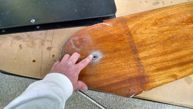
First I clean the tiller & rudder using Interlux 333. Clean the wood before sanding so you don’t drive dirt, salt and anything else collected over the sailing season into the wood. Now sand the rudder & tiller with 220 grit sandpaper. If there is damage to the rudder and/or tiller finish I will sand that location with 120 and then with 220. Be sure to ‘rough up’ the entire piece with 220 to assure you get a good bond between the old and new varnish. The more old varnish removed by sanding requires more new coats of varnish to be applied.
I now follow the steps outlined in my posts on how new rudders and tillers are varnished. See Varnishing Part 1 and Varnishing Part 2.

If the pieces were only lightly sanded with 220 I apply two coats of new varnish. If heavy sanding was required because of damage to the rudder or tiller I apply at least four coats of varnish.
After apply the necessary number of coats to get a nice new finish I allow the last coat to dry for at least two, usually three, days to assure it is fully cured. Now put the tiller/rudder assembly back together in the reverse order it was taken apart.
When you install the compression and pivot bolts make the nuts ‘snug’ to start. You will need to adjust how tight the compression posts and pivot bolts bolts to assure the assembly isn’t too loose (wiggles like an old car’s front end); or are to tight (making it difficult to raise and lower the rudder). Adjustment hints are outlined in the Sage 17 owner’s manual. NOTE: if the bungee cord is tied too lose the rudder will not stay in the up position.
– Dave
NOTE: I originally posted this March 2015 on Sage Marine’s BLOG. In a short time the BLOG will be closed – stupidly. I am reposting this information so it is not lost.
